When we link a Structural Revit file that has structural bracing into an architectural RVT project, 
Revit does NOT show the true cut section in the floor plan (based on the view range settings). For eg. the bracing looks like this in plan:
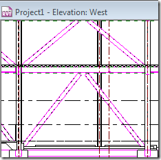
However, if we cut a detail section or callout, it looks like:
which is the correct representation based on the cut plane and view range.
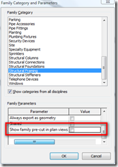
This is unacceptable. Revit should also show the bracing in plan view types correctly. This can lead to lots of coordination issues. To make Revit display the bracing correctly, ask your structural engineer to

After this is done, Revit show the bracing in plan like:
Even though the architect can edit the structural family to make this change, Architect’s edits in the structural file will be overridden when the structural file is updated next time by the architect. So, it is better if the structural engineer makes the edit it.
Thanks to Autodesk Subscription team for this tip.


No comments:
Post a Comment