Friday, October 24, 2008

Deleting a Curtain Wall Grid

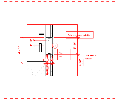
Revit allows us to delete a curtain wall grid very easily. Select the grid (use TAB key if needed) and press the delete button.

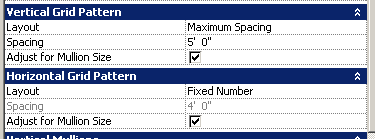
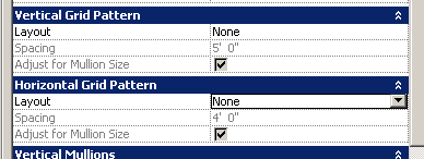
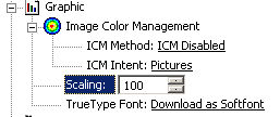
However, if the grid was created using the (out of the box) Storefront type or any other type that 'generated' the grid pattern based on the type parameters, Revit does not allow you to delete it. The type parameters for grid patterns typically look like this:

image

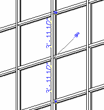
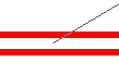
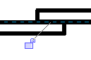
Selecting the grid also shows a pin like this:

image

Unpinning does not allow you to delete it.

To be able to delete the grids, you need to:

  1. Change the Grid Pattern type parameters to none like this:
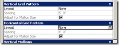
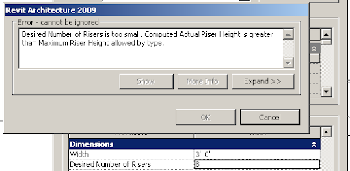
image
    Press ok.
  2. Revit gives a warning that the Type generated gridlines will become non-associated. Press OK. Don't press Delete Gridline button. (You dont have to delete the 'all' the gridlines, right?)
  3. Now Revit allows you to delete any unnecessary grids. You dont even have to unpin them.

It is a good idea to duplicate the CW style before changing the type parameters, so that the change does not affect any other CW.

Revit does not change any default grid patterns or any user edited custom Grid patterns when you choose "none". It just makes the gridlines non associated.

Tuesday, October 21, 2008

Schedule list of Revised Sheets

Question: Is there a way to schedule drawing sheets based on their revision number? For eg., you have a project with a lots of sheets and before issuing a new Revision set, you want to get a list of the sheets that will be issued for this particular revision.

Even though there is a Revision parameter in the sheet properties,
image
it is not exposed in the list of available fields for the Drawing List schedule.
image
So, it looks like getting a list in a schedule form seems to be difficult.

However, you can use browser organization to group the sheets that belong to each revision numbers in the Project Browser. To do this:

  1. Go to Settings menu > Browser organization > sheets tab > New > name it as "Sheets by Revision"
  2. In the Browser Orgn Properties dialog box, in the 'group by' select 'Current Revision' and hit ok.
    image
  3. The project browser now groups the sheets by the current Revision Number.
    image

Monday, October 20, 2008

Print PDF to Half scale from Adobe Reader

Before I start: IF you use Autodesk DWF, you will not have this problem!

Adobe reader 8 does not allow you to print to a certain scale, except for:

image

Some printer drivers allow you to print in a desired scale.

To do this, while in the print dialog box, go to printer properties

image

and change the option for scaling there:

image (Canon copier)

image (HP Designjet)

image (IKON color laser)

image (Oce 600)

Remember to print to full scale from the application (in this case Adobe Reader) with no scaling and select the Paper size that matches the paper size of the PDF document. The printer driver scales and prints in appropriate size and sheet (in Oce!)

Friday, October 17, 2008

Move Floor Plan callouts to another view

Scenario: You have an (original) plan view with some detail / floor plan callouts. Then you have a duplicated view with some Floor plan callouts on it. Now you want to move all the Floor plan callouts from the duplicated view to the original plan view and delete the duplicated view.

I wrote about moving a detail callout view tag from one view to another yesterday.

Creating a reference callout will work, as long as you dont want to delete the duplicate views and you dont want the callout boundary and the crop view of the view are not coordinated / linked.

Instead:

  1. Open the particular Floor plan callout view.
  2. Select all the objects that need to be copied from the Floor plan callout view along with it's view boundary. (Use Filter tool if needed)
    image 
  3. Go to edit menu > Copy to clipboard.
  4. Go the the Original plan view and then to Edit menu > Paste Aligned > Current view.
  5. This results in:
    1. A new Floor Plan callout tag in the original plan view.
    2. The floor plan callout view will contain all the detail elements.
  6. Now you can safely delete the duplicated view. (This deletes the floor plan callouts in duplicated view. However, since we have already created new floor plan callout views, it should be fine. )

Thursday, October 16, 2008

Move detail callouts to another view

Scenario: You have an (original) plan view with some detail callouts. Then you have a duplicated view with some detail callouts on it. Now you want to move all the detail callouts from the duplicated view to the original plan view and delete the duplicated view.

The easiest is to cut and paste the callouts. However, this does not bring the detail elements added to the detail views like dims,  annotation, etc. So, not an option.

You could:

  1. Select the callout detail tag in the duplicated view and go to its properties and change the 'Show in' parameter to 'intersecting views'. 
    image  
    (This makes the detail callout tags visible in the original plan view and if you don't want to delete the duplicated view, you don't have to do anything else!)
  2. If you try to delete the duplicated view, the detail callouts that were created on the duplicated view will get deleted too.
  3. To be able to delete the duplicated view, without deleting the detail callouts, select the callout detail tag and go to its properties and change the 'Parent View' parameter to 'none'
    image

Now the detail callout should be visible in the original view and Revit will allow you to delete the duplicated view without deleting the details. This works only for the detail callouts.

You need to employ a different strategy to move Floor Plan Callouts to another view.

Wednesday, October 15, 2008

Windows Live Writer upload image error

This post is not about Revit.

I had written some time back about posting my blogs using Windows Live Writer. Incorporating screen captures from Revit was very easy using the WLW. However, recently I started getting error messages (The remote server returned an error: (403) Forbidden)

WLW has been saving all the images I uploaded in my blog to an album called "Windows Live Writer" in my picasa account. Once the number of images reaches 500, picasa does not allow anymore images to be uploaded. Hence, the error.

WLW cannot upload to any other folder. (The picasa plugin available for WLW is not suitable for screen captures.) Other options are to use another picasa account to upload images.

Based on the tip here, I have just renamed my picasa album "Windows Live Writer" to "Windows Live Writer 01" and it works great. Even though I have renamed the album, the 500 images that are already linked from this blog still to work fine (!)

sangath 290794

(this is a test pic)

Tuesday, October 14, 2008

Changing level to 100

This is a beginners tip.

Lot of firms want the Ground level (First Level) to be 100'. Or the actual level height given by the civil Engineer. Trying to change the level directly by editing the Revit level won't work. (It might actually move the model and so, all your view crops, etc may become wrong!)

Instead, while in an Elevation view,  go to Tools menu > Project position/orientation > relocate this project... and then click in the drawing area and move your cursor up and enter 100' (or whatever distance you want the levels to move)

Zoom all and view the levels, it would most probably not have changed. Select the level head and go to its type properties and change its Elevation Base to "Shared"

image

That should do it.

Friday, October 10, 2008

Missing Rotation Origin and active worksets

One of our project would not show the rotation origin, which looks like this,

image

while in the rotate command. The stuff it showed looked like:

image

When we aligned two objects, it would not show the customary lock too:

image

No clues yet.

However, when we tried to insert windows / doors, Revit would not show any preview, but would insert them anyway. But it would not show the inserted element! Yet, it shows the opening cut made by these inserted elements!

That's the clue. The current (active) workset is switched off!!!

Thursday, October 9, 2008

Best Practices - Split Level Design

Summary:

  1. Create dedicated Revit Levels for all the change in levels in floor.

  2. Create associated views for all the Revit levels where, you envisage inserting a door / window / wall / room, etc.

  3. Whenever inserting a new element, go to the associated view for that particular Revit Level and then insert the element.

Full Story:

Drawing all the elements in a split level design on the same level (plane) looks great in plan. Until you need to elevate them or add stairs / ramps.


Adding Revit levels respective to the actual change in levels in floors would aid in making the sections / elevation look right (by selecting a wall > move to it's correct base constraint; moving the windows and doors with correct sill levels; etc.)


However, the plan may not look right, because the change in sill level of the windows raised them above the cut plane, etc.


However, you can draw "Plan Regions" (View menu > new > Plan regions) to offset this and everything will be fine.


Any wall or room added into the project automatically lands on the level the current view is associated with. And so, if you need to add a wall, etc. on the raised (lower) floor level, and if you don't have an associated view for the level, you would have to add it in a view associated with a different revit level and later select the particular object and move it to its correct level. Sometimes, if the level difference is too much, the inserted / added object will vanish in front of your eyes, with a Revit warning, because of the view range stuff. (alas, if the object you are adding is a room, you cannot change the level parameter for the room and so you are stuck!)
To circumvent this, you need to create associated views for all the Revit Levels.


To add elements to a particular level, you need to make the view associated to that level current before proceeding.

For printing purposes, you can create an overall plan with Plan Regions to show all elements along with annotations in one view.

Wednesday, October 8, 2008

View Range and cut plane revisited

I read a very nice chart posted on the web (By James Van?) explaining the view range options accessed from the View property. I could not find it anymore and had to make a similar one to explain to our people.

image

The TOP range has always been confusing. Symbolic lines / model lines of elements (for eg. windows) that are above the cut plane, but below the TOP range will show up. Seems like the view is aware of some selected objects in between these ranges, but show them only if it is designed to show inside the family. This option can be used to show upper storey windows / over the head casework.

The <Beyond> linetype can be tweaked in Settings menu > Linetypes... dialog box.

Here is a window at 3' sill level on a view with a cut plane at 4' and a TOP range of 7'-6" (default)

image

The sill level of the window is raised to 7'

image

If the sill level is raised to 8', poof...

image

The following picture shows the model lines that are used to depict the frame in the window family.

image

Tuesday, October 7, 2008

Level of accuracy

Want to create a very simple single flight stair like this:

image

8 risers of 7" each that makes 4'-8". Perfect. But Revit kept giving this error message, when tried with 8 risers. 

image

It actually says "Desired number of Risers too small..."

How can 8 risers be too small? Anyway, it turns out, when the accuracy of the levels was checked, it said.

image

Correcting this resolved the issue. Great!

Now, who is the culprit that actually entered such crazy dimension to that level?

Monday, October 6, 2008

Non-Align two attached walls

Very simple issue.

We have two dissimilar walls that are aligned look like this in plan:

image

image

We want to move one of the walls (brick) so that there is a 2" offset. But moving one of the walls, moves both the walls. Trying to align to a ref plane that is offset by 2", moves both the walls together too.

Selecting the wall, then selecting the Move command and then selecting the disjoin option in the option bar:

image

does the job.

image